Terms
Node
A node is a physical electronic device connected to a network, eg: a computer, printer, router. If set up properly, a node is capable of sending and/or receiving information over a network.
Links
Links connect nodes on a network. Links can be wired, like Ethernet, or wireless, like Wi-Fi. Links to can either be point-to-point, where Node A is connected to Node B, or multipoint, where Node A is connected to Node B and Node C.
Topology
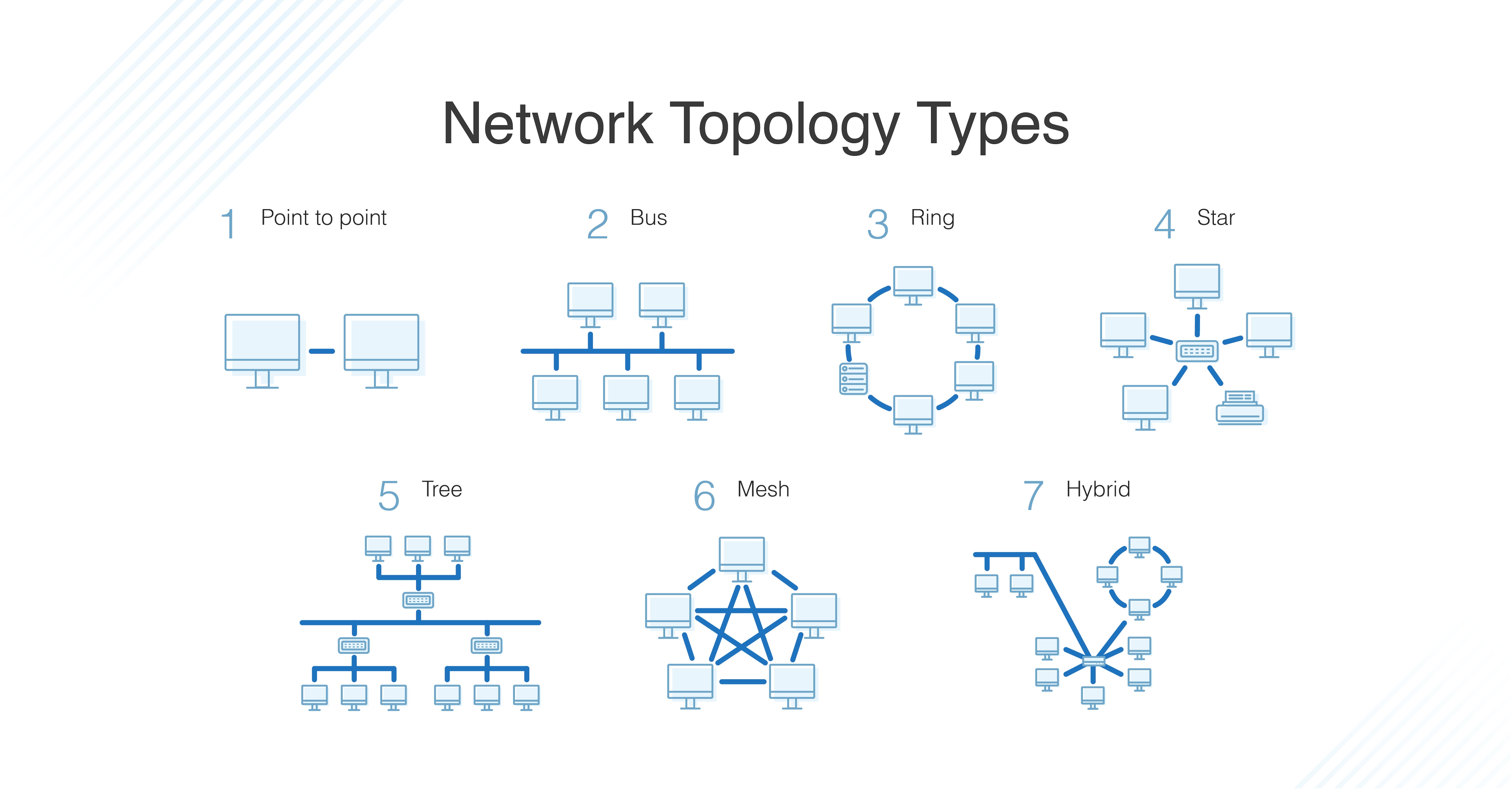
Topology describes how nodes and links fit together in a network configuration, often shows in a diagram. Here are some common network topology types:
The OSI Model: 7 Layers
Layer 1: Physical Layer
Layer 1 contains the infrastructure that makes communication on networks possible.
Tech in Layer 1:
- Nodes (devices) and networking hardware components.
- Device interface mechanics.
How and where does a cable connect to a device (cable connector and device socket)? What is the size and shape of the connector, and how many pins does it have? What dictates when a pin is active or inactive?
- Functional and procedural logic.
What is the function of each pin in the connector - send or receive? What procedural logic dictates the sequence of events so a node can start to communicate with another node on Layer 2?
- Cabling protocols and specifications: Ethernet (CAT), USB, DSL…
- Cable types, Signal Types, Signal transmission method (wired or wireless).
Data Unit on Layer 1: Bit. Nodes can send, receive, or send and receive bits. If they can only do one, then the node uses a simplex mode. If they can do both, then the node uses a duplex mode. If a node can send and receive at the same time, it’s full-duplex – if not, it’s just half-duplex.
Layer 2: Data Link Layer
Layer 2 defines how data is formatted for transmission, how much data can flow between nodes, for how long, and what to do when errors are detected in this flow.
- Line discipline.
Who should talk for how long? How long should nodes be able to transit information for?
- Flow control.
How much data should be transmitted?
- Error control.
detection and correction. All data transmission methods have potential for errors, from electrical spikes to dirty connectors. Once Layer 2 technologies tell network administrators about an issue on Layer 2 or Layer 1, the system administrator can correct for those errors on subsequent layers. Layer 2 is mostly concerned with error detection, not error correction.
2 distinct sublayers within the Layer 2:
- MAC (Media Access Control)
That’s where MAC addresses come from. MAC addr is a unique indentifier for each device on the network.
- LLC (Logical Link Control)
the LLC sublayer handles framing addressing and flow control. The speed depends on the link between nodes, for example Ethernet or Wi-Fi.
Data Unit on Layer 2: Frame. Each frame contains a frame header, body, and a frame trailer:
- Header: typically includes MAC addresses for the source and destination nodes.
- Body: contains of the bits being transmitted.
- Trailer: includes error detection information. CRC (Cyclic Redundancy Check), FCS (Frame Check Sequence), etc.
Typically there is a maximum frame size limit, called an Maximum Transmission Unit, MTU.
Layer 3: Network Layer
The Network Layer allows nodes to connect to the Internet and send information across different networks. Routers are the workhorse of Layer 3. They store all of this addressing and routing information in routing tables.
Data Unit on Layer 3: Packet. Typically, each data packet contains a frame + IP addr.
Once a node is connected to the Internet, it is assigned an IP (Internet Protocol) address, routers use IP addresses in their routing tables. IP addresses are associated with the physical node’s MAC address via the ARP (Address Resolution Protocol), which resolves MAC addresses with the node’s corresponding IP address.
Layer 4: Transport Layer
The Transport Layer provides end-to-end transmission of a message by segmenting a message into multiple data packets; the layer supports connection-oriented and connectionless communication.
Protocols
- TCP: Transmission Control Protocol, a connection-oriented protocol, prioritizes data quality over speed.
- UDP: User Datagram Protocol, a connectionless protocol, prioritizes speed over data quality. UDP does not require a handshake, which is why it’s called connectionless.
TCP and UDP both send data to specific ports on a network device, which has an IP address. The combination of the IP address and the port number is called a socket.
Layer 5: Session Layer
The Session Layer initiates, maintains, and terminates connections between two end-user applications. It responds to requests from the presentation layer and issues requests to the transport layer.
2 important concepts:
- C/S Model (Client/Server)
- Request/Response Model
Protocols:
- NetBIOS
- RPC (Remote Procedure Call)
From here on out (layer 5 and up), networks are focused on ways of making connections to end-user applications and displaying data to the user.
Layer 6: Presentation Layer
The Presentation Layer formats and encrypts data.
- format: ASCII, Unicode, etc.
- encrypt: SSL/TLS, etc.
Layer 7: Application Layer
The Application Layer owns the services and functions that end-user applications need to work. It does not include the applications themselves.
Protocols:
- HTTP (Hypertext Transfer Protocol)
- FTP (File Transfer Protocol)
- SMTP (Simple Mail Transfer Protocol)
- SSH (Secure Shell)
- IMAP (Internet Message Access Protocol)
- DNS (Domain Name System)
- NTP (Network Time Protocol)
- and more…